Low-Speed Axial Compressor Test Rig FRANCC
The FRANCC (Fundamental Research and New Concepts Compressor) low-speed axial compressor test rig is a test rig set up at the Chair of Turbomachinery and Flight Propulsion since 2020, specifically designed for the investigation of new compressor blading concepts. The test rig has the following key parameters:
- Number of stages: 3 + inlet guide vanes (IGV)
- Number of blades IGV-rotor-stator: 40-40-40
- Hub radius / Shroud radius: 440 mm / 550 mm
- Speed: 0...1800 1/min
- Mass flow: 0...22 kg/s
- Drive: Speed-controlled three-phase asynchronous machine, 315 kW
- 7 traverse planes in r-j-direction
The first run of the compressor took place on 06.12.2021, on 02.03.2022 the design speed was reached for the first time.
Description of the Test Rig
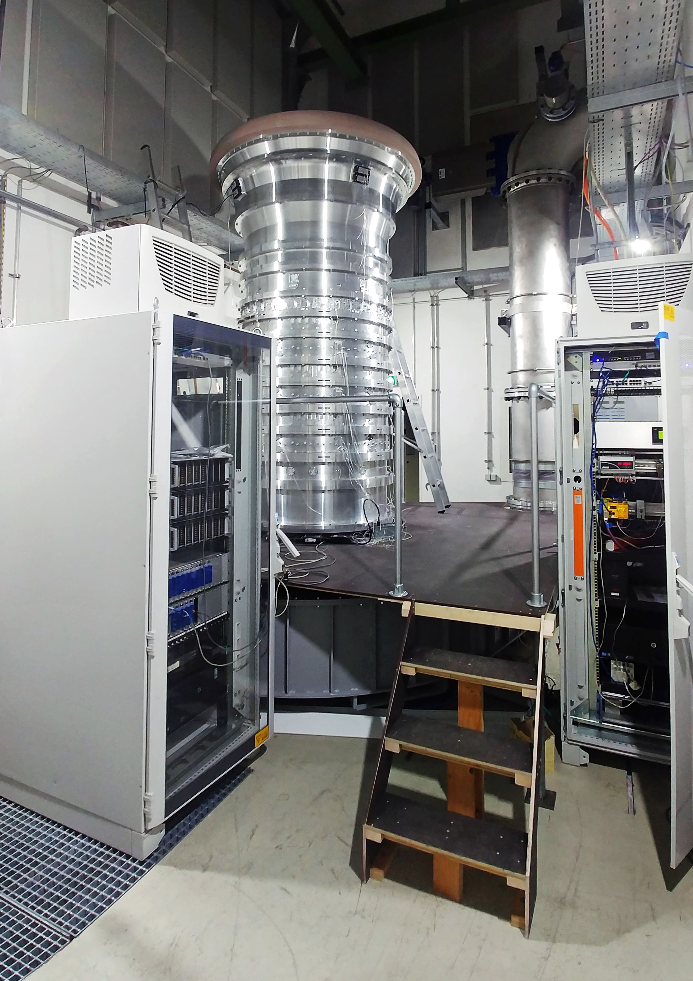
For the greatest possible circumferential uniformity as well as good accessibility, the machine axis is arranged vertically, with the flow passing through the machine from top to bottom. Two interchangeable bearing concepts are available, a conventional robust rolling element bearing and a particularly low-friction air film bearing. The latter is particularly suitable for precise efficiency tests. The following figure 1 shows the test rig.
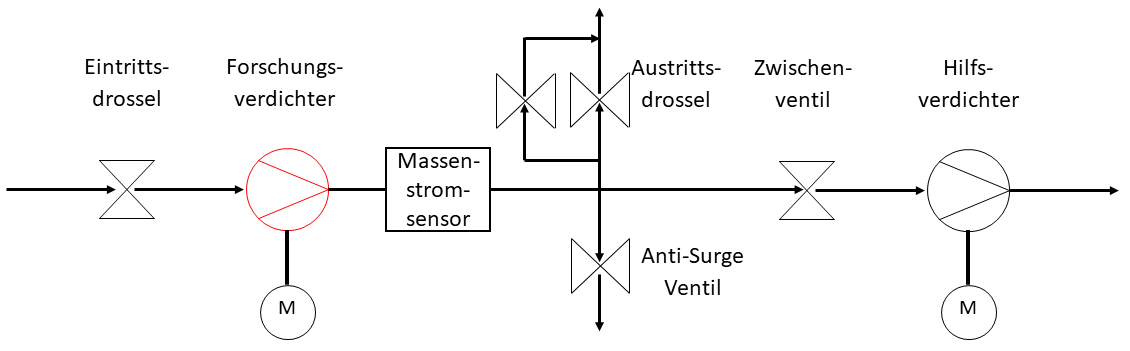
To vary the Reynolds number, the inlet pressure of the compressor can be reduced to 250 mbar via a throttle. For this purpose, the inlet nozzle, which is used for atmospheric operation, is exchanged for the inlet throttle. Since the research compressor has a pressure ratio which is too low for subatmospheric operation, a downstream auxiliary compressor is used in this case to raise the pressure to ambient pressure. The following figure shows schematically the air flow of the test rig for atmospheric and subatmospheric operation.
Instrumentation and Measurement Equipment
For the scientific investigations of the flow phenomena, pressure instrumentation is primarily used. Measuring rakes with 11 radially distributed measuring points each are used to measure the inlet and outlet conditions and thus determine the integral compressor operating point. In each compressor stage, the static wall pressures and the total pressures at the stator leading edges are measured. Transient pressure sensors in the casing wall are used to record the rotor pressure profile and to detect stall in the compressor. Detailed investigations of the flow profile are carried out using aerodynamic probes which can be moved in the r-j-plane behind each blade row in the traversing mechanisms.
The following measurement equipment is available at the test rig:
- 304 relative pressure measuring channels (25 mbar, 68/75 mbar)
- Barometer and absolute pressure sensor 0...1 bar as absolute references
- Up to three reference levels for the relative pressure sensors using high-precision reference sensors
- 2* 10 measuring channels each for Pt100 sensors in 4-wire circuit or 20 thermocouples
- Global mass flow measurement in the exhaust air system
- Torque measurement with two simultaneous measuring ranges for high measuring accuracy
- Speed measurement via inductive sensor
- 3C-2D Stereo PIV system
Applications
The research compressor is used for experimental investigations in the following research projects:
- Unsteady Tandem Flow (You can find detailed information here)
- DRIVER (You can find detailed information here)
Project partner
The build of the test rig is made possible by an approved large-scale equipment application to the German Research Foundation (DFG) and the Forschungsvereinigung Verbrennungskraftmaschinen e.V. (FVV) .
