High Speed Research Compressor
Project History
The project was kicked off in 2013 with the definition of the design requirements for the test vehicle, which is a three-and-a-half stage axial compressor. In 2014 all auxiliary systems were defined in order to prepare the facility for the compressor. Including the expansion of the 20kV power supply, the drive train, inlet- and exit silencers, DAQ and control system, secondary air system and lube oil system. In 2015 most of the components have been delivered and individually commissioned.
The facility is aimed at carrying out research programs with a focus on compressor rear stage technologies including aero, thermal and mechanical disciplines.
First operation of the compressor was achieved on the 8th of April 2016. Design speed was reached a few weeks later.
Due to space constraints particular efforts were put on an in-situ calibration of the nozzle and verification of uniform inflow conditions at the compressor inlet.
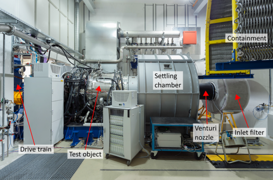
The Bench Setup
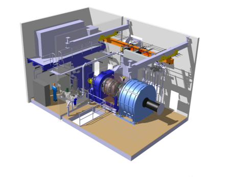
The compressor is driven by a 3MW electrical motor connected to a 1:2.52 gearbox allowing maximum compressor speeds of 5000rpm. Between gearbox and compressor a torque-meter is installed for precise measurements of shaft power to the compressor.
The compressor itself is operated in an open-loop configuration at ambient pressure with a pressure side throttle system. The hydraulically actuated throttle system features a fast opening mode for quick recovery from stall or surge. Inlet- and exhaust piping of the facility allow a maximum volume flow of 45m³/s and exhaust temperatures up to 200°C. A secondary air system with thirteen individual controlled bleed or feed lines allows the measurement and control of rotor seal leakage flows as well as controlling rotor tip clearances by means of controlled casing and rotor cooling.
Instrumentation
The test vehicle is equipped with 570 pressure measurements locations for both, static and total pressure measurements. They are distributed along the flow path casing, the stator leading edges and compressor cavities together with a total of 400 thermocouples for temperature measurement.
Furthermore, 24 dynamic pressure sensors (Kulite) are distributed along the casing at rotor mid-cord and leading edge locations to measure dynamic pressure changes of passing rotor blades which are also used for stall and surge detection. Rotor blades and stator vanes are equipped with a total of 75 strain gauges for monitoring of the excitation of critical modes. A Rotadata Telemetry system is used to transfer the sensor data of blade strain gauges and disc thermocouples from the rotating frame to the stationary frame. The rotor tip clearance is monitored at all stages with three circumferentially distributed capacitive tip clearance probes per stage (MTU BSSM System).
Three-axis traverse gears are used to traverse five-hole and fast response aerodynamic probes in order to acquire 2D flow field measurements behind stator vanes and rotor blades.
Work
The HSRC is used to investigate new concepts and technologies for rear stage compressors at engine-representative Mach numbers. Currently the Institute for Turbomachinery and Flight Propulsion (LTF) is involved in research activities for advanced flow treatments which are tested at the HSRC.
Cooperation
The project was funded by the Bavarian Ministry of Economics, the Technical University of Munich and GE Global Research at Garching, Germany in collaboration with GE Power, GE Aviation and GE Oil & Gas.

Person in charge (copy 5)
[Translate to en:]
- Christian Schäffer, M.Sc.
- Konstantin Speck, M.Sc.
- Dipl.-Ing. Marcel Schmieder
- Dr.-Ing. Christian Helcig